Coordinate Conversion
Click the Map | Coordinate Conversion command or click the  button to open the Coordinate Conversion dialog. A coordinate conversion adjusts the values of the existing map coordinates and moves all objects to the new locations. Coordinate conversions are often used to correct for off-center control points in the original project because you can perform different math operations on the X and Y axis. Coordinates can be adjusted with a math operation or georeferenced. Examples of situations you would use coordinate conversions are: converting the file coordinates of a *.DXF file to latitude/longitude coordinates, or converting a site-specific coordinate system to a regional coordinate system.
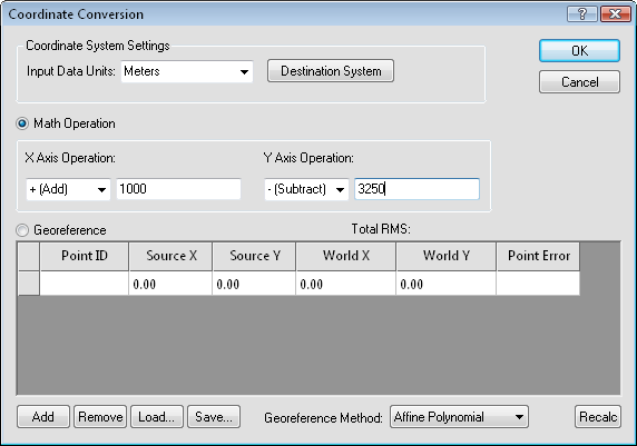
Set the Input Data Units, the Math Operation, or pick points
using the Georeference option in the Coordinate Conversion dialog.
Input Data Units
The Input Data Units defines the data units of the project. This is most often defined by an imported image or vector file. To change the data units, click on the existing option and select the desired coordinate units from the list.
Coordinate System
Click the Destination System button to open the Assign Coordinate System dialog. This dialog lets you define a new output coordinate system during the conversion process, and is useful for transforming site-specific coordinate systems to regional georeferenced projected systems.
Math Operations and Georeferencing
Didger can perform two types of coordinate conversions: Math Operation and Georeference. Both methods convert coordinates but require that you know different information about the data. You can select one or the other in the conversion process.
Math Operation
Use Math Operation when you want to correct a known offset in the project coordinate system. For example, add 0.35 to all X values, or multiple 1.50 from all Y values.
To offset all values by an X or Y value, select the desired operation from the X Axis Operation or Y Axis Operation. Available options are Add, Subtract, Mulitple, and Divide. After selecting the operation, highlight the existing value and type the desired value. For example, to offset all objects by 0.35 units in the X direction and multiply all Y values by 1.5, the Math Operation would be selected and the values set to:
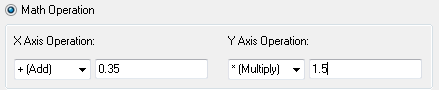
Set the Operation and value for the offset.
Georeference
Use Georeference when you know the exact coordinates of three or more non-linear points and you want to recalibrate based on those values. This is useful when you want to recalibrate a Didger project file. For example, suppose that you know that the image is incorrectly referencing the wrong X value, but that the image is slightly warped. You can select points on the map and type in new values in the georeference table.
Click in the project to set the Source X and Source Y values. Type in the Point ID,
World X, and World Y values. The Point Error is automatically
determined when four or more points are entered.
The Georeference table contains the following information:
-
Point ID lets you enter a value for each point. This is useful when several points are added to the table.
-
The Source X and Source Y columns contain the original XY locations of the project file. Click in the project to enter values in the Source X and Source Y columns.
-
The World X and World Y columns contain the real world coordinates of the project file. Highlight the existing value and type the desired new coordinates into the box.
-
The Point Error column displays the error value for each calibration point between the source X and Y coordinates and referenced image.
Zooming and Panning the Project
After selecting Georeference, click on the project to activate the project window. To zoom in, hold down the SHIFT key on the keyboard or scroll the mouse wheel forward. To zoom out, hold down the CTRL key on the keyboard and click or scroll the mouse wheel backward.
Click on the image and hold the mouse wheel down. The cursor changes to  to indicate pan mode. Drag the mouse around to move the image.
Add
Click Add to add another row to the georeference table. Each row is a new calibration point. The new row is added at the bottom of the table with the default values.
Remove
Click on a row in the georeference table to select it. Click Remove and the currently selected row is deleted from the georeference table.
Load
Click Load to open the Open dialog. Select a previously defined set of calibration points. The calibration points can be stored in any supported data file format, including .XLS, .XLSX, .ACCDB, .TXT, and .DAT. Loading a previously defined set of calibration points saves you the time of typing in the coordinates for a project that you have used in the past. After selecting the new file and clicking Open, the Load Calibration Points dialog appears. Set the columns and click OK and the points are displayed in the georeference table.
To use previously defined calibration points:
-
Click Load. The Open dialog displays.
-
Points may be loaded from any data file format, such as a .DAT, .XLSX, or .ACCDB file. Select the appropriate file in the Open dialog.
-
Click Open.
-
The Load Calibration Points dialog appears.
-
Set the columns to the appropriate columns in the worksheet.
-
Click OK. The values are loaded into Coordinate Conversion dialog in the georeference table.
Save
Click Save to save the calibration points to a file for use at a later point or in another project. After clicking Save, the Save As dialog appears. Type a file name and click Save and the points are saved to an ASCII data file.
Georeference Method
The Georeference Method list lets you select from numerous transformation functions. Available options are Affine Polynomial, First Order Polynomial, Thin Plate Spline, Natural Cubic Spline, Marcov Spline, Exponential Spline, Rational Quadratic Spline, Inverse Distance Squared, Second Order Polynomial and Third Order Polynomial. To change the Georeference Method, click on the existing option and select the desired option from the list. Not all options will be available every time, as the options depend on the number of points in the georeference table. By default, the Affine Polynomial is selected, which works well in many situations.
Total RMS
If you choose to use the georeference option, the Total RMS value is displayed above the georeference table when the Recalc button is clicked. The RMS value is recalculated with the latest set of values.
Recalc
Click Recalc to recalculate the RMS and point errors after selecting new locations for the calibration points.
Example 1: Offsetting Value
Use the Math Operation option to offset the coordinates by a specified amount. You can change X, Y, or both X and Y coordinates by a specified amount.
To convert coordinates with a Math Operation:
-
Click the Map | Coordinate Conversion command.
-
In the Coordinate Conversion dialog, select the Math Operation option.
-
In the X Axis Operation section, click on the existing operation and select the desired type of operation from the list.
-
In the X Axis Operation section, highlight the existing value and type a new value. This is the magnitude of the offset.
-
If desired, set the Y Axis Operation.
-
If desired, set the amount of the Y Axis Operation.
-
Click OK and the entire project is offset by the desired amount.
Example 2: Georeferencing the Project
The Georeference option is similar to calibrating a tablet in that it applies coordinates to the project based on a minimum of three known coordinates. The control points cannot fall into a straight line. See Selecting Calibration Points for more information on selecting calibration points.
To convert coordinates with Georeference:
-
Click the Map | Coordinate Conversion command.
-
In the Coordinate Conversion dialog, select the Georeference option.
-
Click on the record in the table to highlight it.
-
Note that the pointer is a cross hair pointer  . Move the pointer over the project and click on the point where you have known coordinates. A calibration marker is placed at the clicked location, and the values for the Source X and Source Y points are filled into the record. The Source fields show the original coordinate system of the project.
-
Highlight the value in the World X field and enter the X coordinate you want to assign to that point.
-
Highlight the value in the World Y field and enter the Y coordinate you want to assign to that point.
-
Click Add to add another record in the table.
-
Repeat steps 3 through 7 for each reference point you want to define. The Georeference option requires at least three points to define your coordinate system.
-
Set the transformation method in the Georeference Method list for the RMS calculation to be made.
-
If you create four or more calibration points, Didger calculates the RMS error. The overall accuracy of the RMS error varies with the number of reference points, and the selected georeference method.
-
If you are unhappy with the reported RMS values, you can highlight each record in the table and re-digitize the points. Alternatively, you can manually change the value in either the World X and World Y fields, or the Source X and Source Y fields. However, you must press the Recalc button in order to update the reported RMS values.
-
Once the georeference method is selected and you are satisfied with the reported RMS, click OK and the entire project is converted to the new values.
See Also
Set Default Projection
Image Registration and Warping