Image Registration and Warping Dialog
The Image Registration and Warping dialog appears in two places in a Didger project. It appears during File | Import when an non-georeferenced image is imported. It also appears when the Image | Image Registration and Warping command is clicked. Regardless of how the dialog is opened, the image can be calibrated, recalibrated, or georeferenced using the Image Registration and Warping dialog.
In an existing project, click on the image to select it. Click the Image | Image Registration and Warping command or click the  button. The dialog allows you to either verify the calibration or , change the calibration, or define the calibration or coordinate system. The Image | Image Registration and Warping command is only available when there are no other objects in the project and the image is selected. If the Image Registration and Warping command is not available in the Image menu, two options are available. Delete the other objects, leaving only the image. Click on the image and click the Image | Image Registration and Warping command. Alternatively, delete the existing image, leaving the other objects. Click the File | Import command to import the image. The Image Registration and Warping dialog will appear if the image is not calibrated.
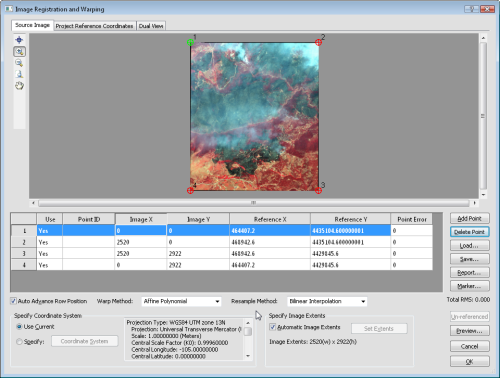
Calibrate the image, set the image projection, and set the warping
method in the Image Registration and Warping dialog.
Image Display
Above the image display window are three tabs: Source Image, Project Reference Coordinates, and Dual View.
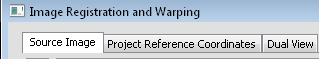
Click on the tab to view information about the image and project.
Click the Source Image tab to display the un-referenced image. Click on the Project Reference Coordinates tab to display the current Didger project. Click on the Dual View tab to display both windows side by side.
Zooming and Panning the Image
On the left side of the image are several buttons for zooming in or out on the image. Click the  button to the left of the image to enter zoom in mode. The cursor changes to
  to indicate zoom in mode. Click on the image to zoom in at the desired location. Click the
  button to the left of the image to enter zoom out mode. The cursor changes to
  to indicate zoom out mode. Click on the image to zoom out at the desired location. Alternatively, click on the image and scroll in or out using the mouse wheel.
Click the  button to the left of the image to zoom out to the entire extents of the image. The full image is displayed.
Click the  button to the left of the image to enter pan mode. Click and hold the mouse button down. The cursor changes to
  to indicate pan mode. Drag the mouse around to move the image. Alternatively, click and hold the mouse wheel down to pan around the image.
Entering Calibration Mode
Click the  button to the left of the image to enter calibration mode. Once calibration mode is entered, the cursor changes to
  to indicate calibration mode. Click on the image where the first calibration point should be located.
Calibration Points
Calibration points are used to define a correlation between the source image coordinates and the project reference system. Didger automatically creates four calibration points, located at the maximum extents of the image. The number and position of the calibration markers shown in any of the selected display windows reflect the number and position of the calibration points. The green marker  indicates the selected row (or calibration point) in the table at the bottom of the dialog. The red markers
  indicate a calibration row that is not currently selected.
Calibration points can be bench marks, surveyed points, grid intersection lines, axis intersections, or any type of identifiable point you choose. At least three calibration points must be entered to accurately calibrate an image. Using more points does not necessarily yield more accurate calibration. Four points are desired, to create a total RMS value and individual point error.
Calibration Points Table
The calibration points table is dynamically linked to the Source Image, Project Reference Coordinates, and Dual View windows when you enter or select the coordinates for calibration points.
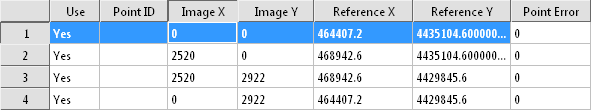
Enter the calibration point information in the calibration point table.
Each row contains information about a specific calibration point. The columns contain information about the location on the image.
-
The Use column contains either Yes or No. This column tells Didger whether to use the point when calibrating. To change the value, double-click on the Yes to change it to No or double-click on the No to change it to Yes. When set to Yes, the calibration point is used for calibrating the image.
-
The Point ID column identify each calibration point with a name. This column is optional and information does not need to be entered into this column.
-
The Image X and Image Y columns contain the pixel location of the calibration points on the image. The 0,0 point is located at the top left corner of the image. The maximum values are determined by the number of pixels in the image. The maximum point is located at the bottom right corner of the image.
-
The Reference X and Reference Y columns contain the real world coordinates of the calibration points. The values can be typed into the Reference X and Reference Y boxes or the point can be clicked on in the Project Reference Coordinates window to be automatically entered.
-
The Point Error column displays the error value for each calibration point between the source image and referenced image.
Auto Advance Row
Check the box next to the Auto Advance Row Position option below the table to automatically move to the next row after clicking on a calibration point. This option makes it quicker to select many calibration points in sequence without needing to click in the table. When unchecked, the current calibration row does not change after clicking a location on the image.
Adding Calibration Points
Click the Add Point button to the right of the calibration point table to add a new calibration point to the image. A new row is added to the table.
Deleting Calibration Points
Click the Delete Point button to the right of the calibration point table to delete the selected row from the table.
Loading Calibration Points
Click the Load button to load existing calibration points into the project. Points may be loaded from any data file format, such as a .DAT, .XLSX, .TXT, or .ACCDB file. Loading a previously defined set of calibration points saves you the time of typing in the coordinates for a project that you have used in the past.
To use previously defined calibration points:
-
Click the Load button.
-
In the Open dialog, select the appropriate file.
-
Click Open.
-
In the Load Calibration Points dialog, set the columns.
-
Click OK. The values are loaded into Image Registration and Warping dialog table.
-
Click on each row in the table and click on the image in the location associated with each row.
-
Click OK and the image is imported with the new calibration.
Saving Calibration Points
Click the Save button to save the calibration points to a file. The Report button displays a generic calibration report of the results, including the calibration RMS value. Check the Auto Advance Row Position box to automatically move to the next record in the table.
Creating a Calibration Report
Click the Report button to generate a Didger Calibration Report. The report opens in a text editor window. The report contains projection information, the axis types, the calibration units, and the calibration points. This can be useful information if you are trying to determine the calibration process used for an image at a later point.
Setting the Calibration Marker
Click the Marker button to set the calibration marker to a different symbol. In the Calibration Marker dialog, set the Symbol Set to the desired font. Any TrueType font on the system can be used for the calibration marker. After the font is selected, click on the desired symbol to select it. Click OK and the new symbol is used for the calibration markers. Click Cancel and the old symbol is still used. By default the  is used for the calibration marker. The marker is green when the calibration point is selected and red when the calibration point is not selected.
Total RMS
The Total RMS value is displayed just below the Marker button. The Total RMS helps you determine the accuracy of your calibration. A large Total RMS could reflect either too few calibration points, or it may mean that you need to recalibrate your image with more accuracy.
Warp Method
The Warp Method option determines the image warping method. Available options are: Affine Polynomial, 1st Order Polynomial, Thin Plate Spline, Natural Cubic Spline, Marcov Spline, Exponential Spline, Rational Quadratic Spline, Inverse Distance Squared, 2nd Order Polynomial, and 3rd Order Polynomial. The default option is Affine Polynomial. To change the Warp Method, click the down arrow next to the existing warp method and select the desired method from the list. Refer to each specific page for the transformation information and an image demonstrating the warp.
Resample Method
The Resample Method option determines the method used to when resampling an image during warping. Available options are Nearest Neighbor or Bilinear Interpolation. To change the Resample Method, click on the down arrow next to the existing resampling method and select the desired method from the list.
The Nearest Neighbor method locates the center of each new image cell and locates equivalent centers on the original image. The closest cell on the original image is assigned to the new image cell. When the original image and the new image differ in size, more than one original cell may be applied to the new image and some original image cells are not applied to the new image. The nearest neighbor method is the fastest resampling method, though it can result in distorted output if the original image and new images differ in size. This method is best for cells containing discrete data.
The Bilinear Interpolation method uses a weighted average of four cells in the original image and applies this to the new image. The new image is smoothed compared to the original image. This method is best for continuous data.
Specify Coordinate System
The current coordinate system is displayed in the bottom left side of the Image Registration and Warping dialog.
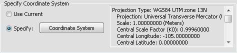
Set the Coordinate System in the Specify Coordinate System section.
If you want to use the current coordinate system, select the Use Current option. Otherwise, select the Specify option to enable to the Coordinate System button. Click the Coordinate System button to open the Assign Coordinate System dialog. Set the coordinate system for the image in your current Didger project. This is the coordinate system that the image is currently displaying.
Specify Image Extents
Check the box next to the Automatic Image Extents option to use the default map extents, image extents, and scaling. The Image Extents values are displayed below the Automatic Image Extents box. For example you may import an image and the Image Extents value may read 515(w) x 515(h). This means the original image was imported with a width of 515 pixels and a height of 515 pixels.
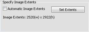
Set the image extents in the Specify Image Extents section.
If Automatic Image Extents is not checked, the Set Extents button is enabled. Click the Set Extents button to open the Change Output Limits dialog and specify the output extents for the map, change the pixel dimensions of the image, or change the scaling. This is useful if you want to create a subset image with a certain extent from the original file.
Preview
Click the Preview button to open the Warp Preview window. A scaled down version of the warped image is displayed. This preview does not use the entire image to display results and therefore, it has a slightly different appearance than the final image will look.
Import without Referencing and Warping
If you do not want the image to be georeferenced, calibrated, or warped, but still want to load it into your Didger project, click the Un-referenced button. This imports the image and allows you to manually move it around in the project window using your mouse.
Resizing the Dialog
To make the Image Registration and Warping dialog larger or smaller, click and drag on the lower left corner of the dialog. When the dialog is the desired size, release the mouse button.
OK or Cancel
Click OK to save the calibration and apply the new coordinates to the image. Click Cancel to exit the Image Registration and Warping dialog without applying the new coordinates.
Example 1: Calibrating an Image by Entering Coordinates
If you know the coordinates of at least three points on your image enter the Reference X and Reference Y coordinates in the calibration points table.
To calibrate the image with three or more known points:
-
Click the Source Image tab at the top of the Image Registration and Warping dialog.
-
In the calibration points table, select the first calibration point.
-
Enter the coordinates of that calibration point in the Reference X and Reference Y cells.
-
Use the , , , or buttons in the Source Image window to move the view to the location of that calibration point.
-
Click the button to enter calibration mode.
-
Click on the calibration point location in the Source Image window.
-
Repeat steps 2 through 6 for each calibration point.
Example 2: Calibrating an Image by Selecting Reference Points in an Existing Project
If you do not know the exact coordinates of three or more points on your image, but you do know where in the project the image is supposed to be located, you can use the Project Reference Coordinates page to help calibrate the image.
To calibrate with reference points on an image:
-
Click the Dual View tab at the top of the Image Registration and Warping dialog.
-
In the calibration points table, select the first calibration point.
-
Use the , , , or buttons in the Source Image window (image on the left) to move the view to the location of that calibration point.
-
Click the button to enter calibration mode.
-
Click on the calibration point location in the Source Image window (image on the left). The pixel location of that point is entered in the Image X and Image Y fields.
-
Use the , , , or buttons in the Project Reference Coordinates window (image on the right) to move the view to the location of that calibration point.
-
Click the button and click on the calibration point location in the project in the Project Reference Coordinates window. The coordinates of that point are entered in the Reference X and Reference Y cells.
-
Repeat steps 2 through 7 for each calibration point.
See Also
Calibration and Georeferencing
Image Menu Commands