Vectorize Image
Click
the Image | Vectorize Image command
or click the  button
to open the Vectorize Image dialog.
The Vectorize Image dialog controls
the settings that automatically convert an image into a vectorized data
set. A complete image can
be vectorized, select colors on the image can be vectorized, noise can
be removed, polygons or polylines created, and a number of other image
processing options are available.
button
to open the Vectorize Image dialog.
The Vectorize Image dialog controls
the settings that automatically convert an image into a vectorized data
set. A complete image can
be vectorized, select colors on the image can be vectorized, noise can
be removed, polygons or polylines created, and a number of other image
processing options are available.
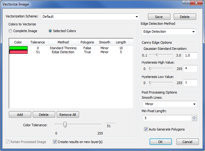
Set the colors to vectorize and the edge detection options
in the Vectorize Image dialog.
Vectorization Scheme
The Vectorization Scheme saves
the settings for different vectorization types to use again on similar
images, without resetting or remembering all the parameters. To change
the Vectorization
Scheme, click on
the down arrow next to the current scheme name and select the desired
scheme from the list.
To create a new Vectorization
Scheme, set all of
the parameters in the dialog. Type a name in the Vectorization Scheme box.
Click Save
to the right of the scheme
name to store the scheme to a file.
To delete an existing
Vectorization
Scheme, click on
the down arrow next to the current scheme name. Select the desired scheme
from the list. Click Delete
to the right of the
scheme name and Save
button.
Colors to Vectorize
Didger
gives you the option to vectorize an entire image or specific colors or
color ranges from the image. To vectorize the entire image, select the
Complete Image option in the
Colors to Vectorize section.
To vectorize only certain colors or ranges of colors, select Selected
Colors in the Colors
to Vectorize section. For example, you may only want
to vectorize the blue rivers on a contour map.
To set specific colors, select the
Selected Colors option. Move
the cursor over the image, and the cursor changes to  .
Click on the color you want to select.
.
Click on the color you want to select.
To zoom into the image, press and
hold the SHIFT key on the keyboard and click on the image. To zoom out
of the image, press and hold the CTRL key on the keyboard and click on
the image. Alternatively, use the mouse scroll wheel to zoom in and out.
To move around on the image, click on the scroll bars to move up/down
or right/left. Alternatively, press and hold the mouse scroll wheel down
and drag the image on the screen.
Once the color is selected,
it is entered into the Color
column cell in the
Vectorize
Image dialog. If
you make a mistake or click the wrong color, simply click again on the
intended color on the image to update the color in the Color column
cell.
To add a new color to the
list, click Add
below the color section.
To delete a color from the list, click on the color in the dialog and
click Delete
below the color section.
To delete all of the selected colors, click Remove
All.
Color Tolerance
The Color Tolerance determines
the range of colors identified by each color. The value is reported in
the Tolerance
column. Tolerance defines
a similarity in color from one pixel in an image from another pixel in
that same image. For instance, the blue rivers might be a darker value
than the lighter colored lakes. If you only want the blue rivers vectorized,
then you want the tolerance value low so the range of blue does not include
the lighter blue lakes. Pixel values can range from 0 to 255. A low color
tolerance is very similar to the pixel color selected. A high color tolerance
fills the pixels within a broader range. Click and drag the  to the right to broaden the pixel range of color. The tolerance number
moves up as the slider moves right. This is useful for color images that
have a variety of pixel color ranges near the edge or border. When the
Color
Tolerance value is
zero, only the selected color is vectorized.
to the right to broaden the pixel range of color. The tolerance number
moves up as the slider moves right. This is useful for color images that
have a variety of pixel color ranges near the edge or border. When the
Color
Tolerance value is
zero, only the selected color is vectorized.
Edge Detection Method
The Edge
Detection Method determines how lines in the image are found. Available
options are Edge Detection, Standard Object Thinning, and Enhanced Object Thinning. To change
the option, click on the down arrow to the right of the existing option
and select the desired option from the list.
If an image was previously
processed using edge detection, erosion,
dilation or one of the other
processing filters, you should select Enhanced
Object Thinning as
the edge detection method from the list. If the image was not pre-processed,
then either Edge Detection or Standard Object Thinning should be selected
from the list for best results.
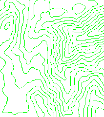
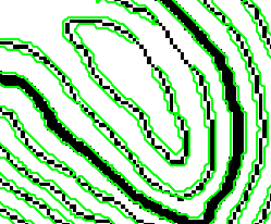
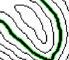
For
most images that contain lines that should be vectorized, Standard
Object Thinning is recommended because lines in images are generally
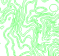
a few pixels wide. The Edge Detection
method would create a polyline on both sides of the line in the image.
Standard Object Thinning creates
one polyline through the middle of the line in the image.
|
|
|
The green lines
are the vectors created using the Standard
Object Thinning method. |
|
The green lines
are the vectors created using the Edge
Detection method. |
Canny Edge
Options
Edge detection is useful for vectorization
processing because it easily detects the edges of lines or color boundaries
in an image and creates single pixel width polylines along the edges.
The Canny Edge Options are only
available when the Edge Detection Method
is set to Edge Detection. If
the options are not available, set the Edge
Detection Method to Edge Detection.
There are three options available in the Canny
Edge Options section: Gaussian
Standard Deviation, Hysteresis High Value, and Hysteresis
Low Value.
Gaussian Standard Deviation
The Gaussian
Standard Deviation is used to smooth the image and look for horizontal,
vertical, and diagonal edges. To change the value, highlight the existing
value and type a new value. Alternatively, click and drag the
to the right or left. The value ranges between 0.1 and 3. Didger
creates a convolution mask
based on the value input. The 0.1 value creates shorter and more fragmented
lines across the image. A 3.0 value creates longer, more continuous lines
across the image.
Hysteresis High Value and Hysteresis Low Value
Hysteresis helps to connect lines
based on angles and pixel value connectivity. To achieve this, hysteresis
uses two different threshold values: Hysteresis
High Value and Hysteresis Low
Value. To change the value, highlight the existing value and type
a new value. Alternatively, click and drag the to the
right or left. The values range between 0 and 255. The Hysteresis
High Value marks out the strongest edges of an image. Hysteresis
traces these high value edges through the image. The Hysteresis
Low Value traces faint sections of lines and avoids the few noisy
pixels that do not constitute a line. Together these high and low values
are able to identify edges and continuity in an image. Typically, the
higher threshold can be set to approximately three times the lower threshold.
|
|
|
The
green lines are the output from the Vectorize
Image command
using Edge Detection
with
an Hysteresis
High Value =
30 and Hysteresis Low Value
=
10. |
|
The green lines are
the output from the Vectorize
Image command
using Edge Detection
with
an Hysteresis
High Value =
70 and Hysteresis Low Value
=
210. |
Post
Processing Options
The Post
Processing Options section contains options to control the final
output of the vectorize command. This can generate smoother, longer lines
or create polygons if a vectorized object appears closed.
Smooth Lines
The Smooth
Lines option reduces the total number of vertices created along
a polyline during the vectorization process. Available options are: No Smoothing, Minor, Moderate,
and Aggressive. The default option
is Minor, which applies a slight
amount of smoothing to the vectorized lines. To change the amount of smoothing,
click on the down arrow next to the existing option and select the desired
option from the list.
For example, a polyline generated
with No Smoothing creates many
points and jagged edges. Setting the Smooth
Lines to Minor removes
some of the points and smooths the jagged edges to make smoother lines.
Selecting Moderate
for the Smooth Lines option reduces
the number of points created during the trace without overly compromising
the shape of the polyline. Selecting Aggressive
for the Smooth Lines option reduces
the number of points even further and simplifies the shape of the polyline.
Some sections of the polyline may be removed with the Aggressive
option.
Minimum Pixel Length
The Min
Pixel Length option is the minimum number of pixels traced before
a new polyline segment is created. To change the value, highlight the
existing value and type a new value or use the  to increase
or decrease the value. Values range from 0 to 255.
to increase
or decrease the value. Values range from 0 to 255.
The default is 10 pixels, which means
that 10 pixels must be connected before a polyline object is created.
Increasing this number results in fewer vectorized polylines with longer
lengths. Decreasing this number results in more vectorized polylines,
with potentially shorter lengths.
Auto Generate Polygons
The Auto
Generate Polygons option is used to create polygons from the vectorized
image when a polyline appears to close. Check the box to automatically
create polygons. When the box is unchecked, polylines are created. The
polylines can be converted to polygons by clicking the Draw
| Change Boundary Type | Polyline to Polygon command after the vectorization
is complete.
Retain Processed
Image
The Retain
Processed Image option is only available when the Colors
to Vectorize is set to Complete
Image. If the Retain Processed
Image is not available, select Complete
Image in the Colors to Vectorize
section. When the box next to Retain
Processed Image is checked, the altered processed
image replaces the current image on the screen. When the box is unchecked,
the original image remains on the screen.
Create
Results on New Layers
The Create
results on new layer(s) option adds the vectorized polylines and
polygons to a new layer. This makes it easy to separate the image layer
from the vectorized information. This option is checked by default. Uncheck
the box next to Create results on new
layer(s) to create the vectorized polylines and polygons on the
same layer as the image.
OK or Cancel
Click OK
to create polylines and polygons from the image. Click Cancel
to close the dialog without creating any polylines or polygons from the
image.
See
also
Processing Filters
Image Registration and Warping
Processing
Filters
Edge Detection