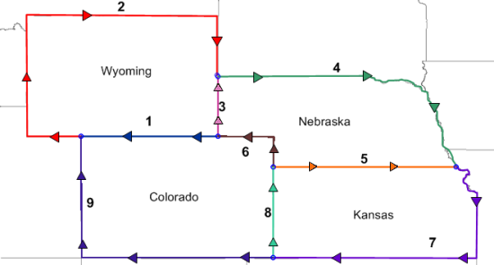
To create polygons from shared borders, the polygons need to be digitized in sections, separating the shared borders from the non-shared borders. Starting with the state of Wyoming in the image, there are three lines that need to be drawn separately. In the image below, these are marked as 1, 2, and 3. Lines 1 and 3 are shared between Wyoming and another state that we may be interested in digitizing. Line 2 belongs only to Wyoming. The other non-shared polyline borders are lines 4, 7, and 9 in the image below.
The image above shows the nine lines that need to be digitized.
The arrows indicate direction for each line to be digitized.
When assigning IDs to each line, the Primary ID will be used as the object name on the left side of the polyline. The Secondary ID will be used as the object name on the right side of the polyline. In these non-shared objects, only a single ID will be entered. Because of the arrow directions indicated in the image above, all of these non-shared objects will only have the right side of the object named.
To digitize the outside edge (non-shared) lines:
Click the Draw | Polyline command or click the  button.
In the Property Manager, click the  next to Increment Settings.
Check the box next to Enter Data After Creation option, if it is not already checked.
Check the box next to Create Several, if it not already checked.
On line 2 (the red line on the outside left edge of Wyoming in the image above),
Click on the bottom-most point, where lines 1, 2, and 9 meet.
For straight-line segments, only points that define direction changes need to be clicked. Click on the far bottom corner on line 2.
Click on the top left corner on line 2.
Click on the top right corner on line 2.
Double-click on the final point, where lines 2, 3, and 4 meet.
In the Enter Object Data dialog, type in Wyoming in the Secondary box.
Click OK.
To create line 4 above,
Click on the first point, where lines 2, 3, and 4 meet. Try to click inside the snap tolerance circle created by the previously digitized line.
Click on the far right straight line edge.
Hold down the mouse left button and drag the mouse along the ragged edge along the rest of the top and far right side of Nebraska.
When the end of the state is reached, press ENTER on the keyboard to end digitizing mode.
In the Enter Object Data dialog, type in Nebraska in the Secondary box.
Click OK.
To create line 7 above,
Click on the first point, where lines 4, 5, and 7 meet. Try to click inside the snap tolerance circle created by the previously digitized line.
Hold down the mouse left button and drag the mouse along the ragged edge along the far right side of Kansas.
When you reach the straight line segment, release the mouse button. Move the mouse to the bottom right corner of line 7 and click the mouse button.
Click on the far left bottom corner on line 7.
In the Enter Object Data dialog, type in Kansas in the Secondary box.
Click OK.
To create line 9 above,
Click on the first point, where lines 7, 8, and 9 meet. Try to click inside the snap tolerance circle created by the previously digitized line.
Click on the far left bottom corner on line 9.
Click on the far left top corner on line 9.
In the Enter Object Data dialog, type in Colorado in the Secondary box.
Click OK.
Press the ESC key on the keyboard to end drawing mode.
Back to Setting the Snap Tolerance
Next to Digitizing the Shared Polylines